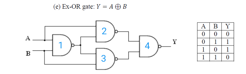
Implementation of Ex-OR Gate using NAND gate
Aim
To study and verify the Implementation of Ex-OR Gate using NAND gate.Learning Objectives
- To understand the behavior and demonstrate Implementation of EX-OR Gate using NAND gate.
- To apply knowledge of the fundamental gates to create truth tables.
- To develop digital circuit building and troubleshooting skills.
- To understand key elements of TTL logic specification or datasheets.
IC Used
| IC Number | IC Name |
|---|---|
| 74LS00 | Quad 2-input NAND Gates |
Circuit Tutorials:
Procedure
- Place the IC on IC Trainer Kit.
- Connect VCC and ground to respective pins of IC Trainer Kit.
- Implement the circuit as shown in the circuit diagram.
- Connect the inputs to the input switches provided in the IC Trainer Kit.
- Connect the outputs to the switches of O/P LEDs
- Apply various combinations of inputs according to the truth table and observe the condition of LEDs.
- Note down the corresponding output readings for various combinations of inputs.
- Power Off Trainer Kit, disconnect all the wire connections and remove IC's from IC-Base.
Theory
Ex-OR GATE - The full form of Ex-OR gate is Exclusive-OR gate. Its function is the same as that of OR gate except for some cases, when the inputs having an even number of ones.
In other words, the output of an Exclusive-OR gate ONLY goes “HIGH” when its two input terminals are at “DIFFERENT” logic levels with respect to each other. The Exclusive-OR Gate function, or Ex-OR for short, is achieved by combining standard logic gates together to form more complex gate functions that are used extensively in building arithmetic logic circuits, computational logic comparators and error detection circuits.
The two-input “Exclusive-OR” gate is basically a modulo two adder, since it gives the sum of two binary numbers.
Boolean Expression Y = A.B' + 'A.B = (A ⊕ B)
"If inputs having an odd number of ones, then Y is true"
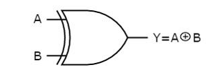
Ex-OR gate operation is similar to that of OR gate, except for a few combinations of inputs. The output of Ex-OR gate is ‘1’ when an odd number of ones present at the inputs. Hence, the output of Ex-OR gate is also called as an odd function.
NAND gate - It is a digital circuit that has two or more inputs and produces an output, which is the inversion of logical AND of all those inputs.
Logic NAND Gates are available using digital circuits to produce the desired logical function and is given a symbol whose shape is that of a standard AND gate with a circle, sometimes called an "inversion bubble" at its output to represent the NOT gate symbol with the logical operation of the NAND gate.
As with the AND function seen previously, the NAND function can also have any number of individual inputs and commercial available NAND Gate IC's are available in standard 2, 3, or 4 input types. If additional inputs are required, then the standard NAND gates can be cascaded together to provide more inputs.
Boolean Expression Y = (A.B)'
"If either A or B are NOT true, then Y is true"
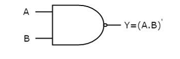
NAND gate operation is same as that of AND gate followed by an inverter. That's why the NAND gate symbol is represented like that.
Block Diagram
Precautions
- Make the connections according to the IC pin diagram.
- The connections should be tight on trainer kit.
- The Vcc and ground should be applied carefully at the specified pin only.
Conclusion
We have learned the Implementation of Ex-OR Gate using NAND gate.Recommendations
Hex Inverting NOT Gate
Aim: To study and verify the truth table of Hex Inverting NOT Gate.
ICs used: 74LS04 Implementation of AND Gate using NOR gate
Aim: To study and verify the Implementation of AND Gate using NOR gate.
ICs used: 74LS02 Implementation of NOR Gate using NAND gate
Aim: To study and verify the Implementation of NOR Gate using NAND gate.
ICs used: 74LS00 Dual 4-Input AND Gates
Aim: To study and verify the truth table of Dual 4-Input AND Gates
ICs used: 74LS21 Implementation of NAND Gate using NOR gate
Aim: To study and verify the Implementation of NAND Gate using NOR gate.
ICs used: 74LS02