
Learning Objectives
- To understand the behavior and demonstrate the Implementation of Binary to Gray code converter using logic gates.
- To apply knowledge of the fundamental gates to create truth tables.
- To develop digital circuit building and troubleshooting skills.
- To understand key elements of TTL logic specification or datasheets.
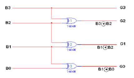
Integrated Circuits Used

Circuit Tutorials

Procedure
- Place the IC on IC Trainer Kit.
- Connect VCC and ground to respective pins of IC Trainer Kit.
- Implement the circuit as shown in the circuit diagram.
- Connect the inputs to the input switches provided in the IC Trainer Kit.
- Connect the outputs to the switches of O/P LEDs
- Apply various combinations of inputs according to the truth table and observe the condition of LEDs.
- Note down the corresponding output readings for various combinations of inputs.
- Power Off Trainer Kit, disconnect all the wire connections and remove IC's from IC-Base.
Theory
Binary to Gray Code - In computers, we need to convert binary to gray and gray to binary. The conversion of this can be done by using two rules namely binary to gray conversion and gray to binary conversion. Binary code is a very simple representation of data using two values such as 0’s and 1’s, and it is mainly used in the world of the computer. The binary code could be a high (1) or low (0) value or else even a modify in value. Gray code or reflected binary code estimates the binary code nature that is arranged with on & off indicators, usually denoted with ones & zeros. These codes are used to look at clarity as well as error modification in binary communications.
Gray Code system is a binary number system in which every successive pair of numbers differs in only one bit. It is used in applications in which the normal sequence of binary numbers generated by the hardware may produce an error or ambiguity during the transition from one number to the next.
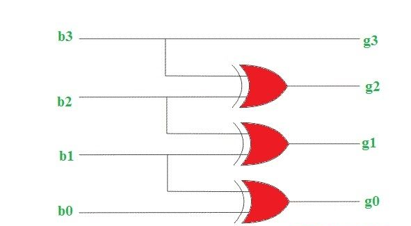
The conversion of binary to gray code can be done by using a logic circuit. The gray code is a non-weighted code because there is no particular weight is assigned for the position of the bit. A n-bit code can be attained by reproducing a n-1 bit code on an axis subsequent to the rows of 2n-1, as well as placing the most significant bit of 0 over the axis with the most significant bit of 1 beneath the axis.
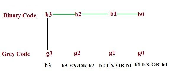
This method uses an Ex-OR gate to perform among the binary bits. In this conversion method, take down the MSB bit of the present binary number, as the primary bit or MSB bit of the gray code number is similar to the binary number. To get the straight gray coded bits for generating the corresponding gray coded digit for the given binary digits, add the primary digit or the MSB digit of binary number toward the second digit & note down the product next to the primary bit of gray code, and add the next binary bit to third bit then note down the product next to the 2nd bit of gray code. Similarly, follow this procedure until the final binary bit as well as note down the outcomes depending on EX-OR logic operation to generate the corresponding gray coded binary digit.
Block Diagram
Precautions
- Make the connections according to the IC pin diagram.
- The connections should be tight on trainer kit.
- The Vcc and ground should be applied carefully at the specified pin only.
