Learning Objectives
- To understand the behavior and demonstrate the operation of 3-Bit Up Counter.
- To apply knowledge of the fundamental gates to create truth tables.
- To develop digital circuit building and troubleshooting skills.
- To understand key elements of TTL logic specification or datasheets.
Integrated Circuits Used

Circuit Tutorials
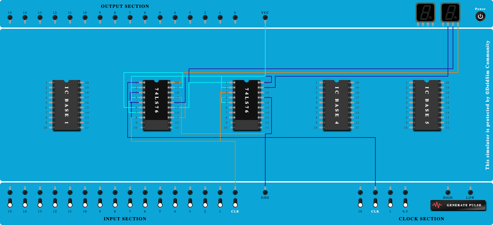
Procedure
- Place the IC on IC Trainer Kit.
- Connect VCC and ground to respective pins of IC Trainer Kit.
- Implement the circuit as shown in the circuit diagram.
- Connect the inputs to the input switches provided in the IC Trainer Kit.
- Connect the outputs to the switches of O/P LEDs
- Apply various combinations of inputs according to the truth table and observe the condition of LEDs.
- Note down the corresponding output readings for various combinations of inputs.
- Power Off Trainer Kit, disconnect all the wire connections and remove IC's from IC-Base.
Theory
Counter - In digital logic and computing, a Counter is a device which stores (and sometimes displays) the number of times a particular event or process has occurred, often in relationship to a clock signal. Counters are used in digital electronics for counting purpose, they can count specific event happening in the circuit. For example, in UP counter a counter increases count for every rising edge of clock. Not only counting, a counter can follow the certain sequence based on our design like any random sequence 0,1,3,2... .They can also be designed with the help of flip flops.flip-flops. It is a group of flip-flops with a clock signal applied.
Counters are broadly divided into two categories -- Asynchronous or ripple counters.
- Synchronous counters.
Asynchronous or Ripple Counters - In asynchronous counter we don’t use universal clock, only first flip flop is driven by main clock and the clock input of rest of the following counters is driven by output of previous flip flops. We can understand it by following diagram.
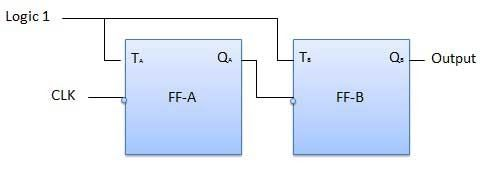
The toggle (T) flip-flop are being used. But we can use the JK flip-flop also with J and K connected permanently to logic 1. External clock is applied to the clock input of flip-flop A and QA output is applied to the clock input of the next flip-flop i.e. FF-B.
Synchronous Counters - Unlike the asynchronous counter, synchronous counter has one global clock which drives each flip flop so output changes in parallel. The one advantage of synchronous counter over asynchronous counter is, it can operate on higher frequency than asynchronous counter as it does not have cumulative delay because of same clock is given to each flip flop.
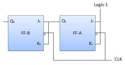
The JA and KA inputs of FF-A are tied to logic 1. So FF-A will work as a toggle flip-flop. The JB and KB inputs are connected to QA.
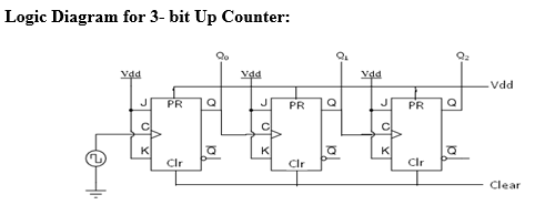
Block Diagram
Precautions
- Make the connections according to the IC pin diagram.
- The connections should be tight on trainer kit.
- The Vcc and ground should be applied carefully at the specified pin only.
Conclusion
Related Study Materials

3-Bit Down Counter

To study and Verify the 3-Bit Down Counter.
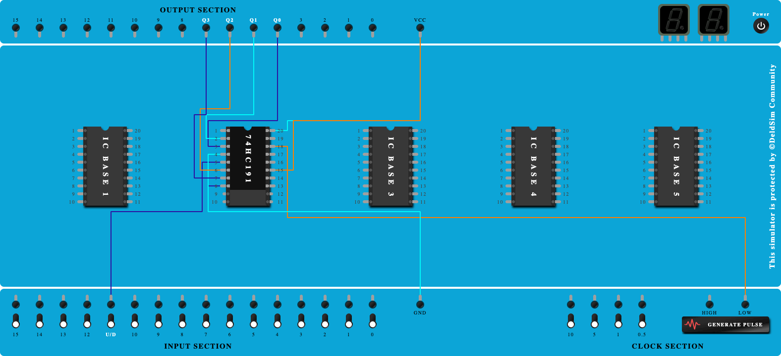
4 bit Up/Down Counter using 74HC191
To study and Verify the 4 bit Up/Down Counter using 74HC191.
4-Bit Up Counter
To study and Verify the 4-Bit Up Counter.

4-Bit Down Counter
To study and Verify the 4-Bit Down Counter.
Design and Verify the operation BCD ripple counter using JK flip-flops
To study, design and Verify the operation BCD ripple counter using JK flip-flops.