Implementation of 4-Bit Magnitude Comparator using IC-74LS85
Aim
To study and Implement 4-Bit Magnitude Comparator using IC-74LS85.Learning Objectives
- To understand the behavior and demonstrate the Implementation of 4-Bit Magnitude Comparator using IC 74LS85.
- To apply knowledge of the fundamental gates to create truth tables.
- To develop digital circuit building and troubleshooting skills.
- To understand key elements of TTL logic specification or datasheets.
IC Used
| IC Number | IC Name |
|---|---|
| 74LS85 | 4-Bit Magnitude comparators |
Circuit Tutorials:
Procedure
- Place the IC on IC Trainer Kit.
- Connect VCC and ground to respective pins of IC Trainer Kit.
- Implement the circuit as shown in the circuit diagram.
- Connect the inputs to the input switches provided in the IC Trainer Kit.
- Connect the outputs to the switches of O/P LEDs
- Apply various combinations of inputs according to the truth table and observe the condition of LEDs.
- Note down the corresponding output readings for various combinations of inputs.
- Power Off Trainer Kit, disconnect all the wire connections and remove IC's from IC-Base.
Theory
4-Bit Magnitude Comparator - Comparators with three output terminals and checks for three conditions i.e greater than or less than or equal to is magnitude comparator. The Comparator is another very useful combinational logic circuit used to compare the value of two binary digits. A magnitude digital Comparator is a combinational circuit that compares two digital or binary numbers in order to find out whether one binary number is equal, less than or greater than the other binary number. We logically design a circuit for which we will have two inputs one for A and another for B and have three output terminals, one for A > B condition, one for A = B condition and one for A < B condition.
Digital Magnitude Comparators are made up from standard AND, NOR and NOT gates that compare the digital signals present at their input terminals and produce an output depending upon the condition of those inputs. Here, two 4-bit words (“nibbles”) are compared to each other to produce the relevant output with one word connected to inputs A and the other to be compared against connected to input B as shown below.
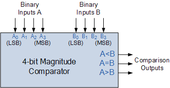
It can be used to compare two four-bit words. The two 4-bit numbers are A = A3 A2 A1 A0 and B3 B2 B1 B0 where A3 and B3 are the most significant bits. It compares each of these bits in one number with bits in that of other number and produces one of the following outputs as A = B, A < B and A>B.
Block Diagram
Precautions
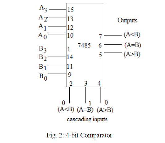
- Make the connections according to the IC pin diagram.
- The connections should be tight on trainer kit.
- The Vcc and ground should be applied carefully at the specified pin only.
Conclusion
We have learned the Implementation of 4-Bit Magnitude Comparator using IC-74LS85.Recommendations
One Bit Comparator
Aim: To study and verify the One Bit Comparator.
ICs used: 74LS0474LS0874LS02 One Bit Comparator using 74LS86
Aim: To study and verify the One Bit Comparator using 74LS86.
ICs used: 74LS8674LS0474LS08 8 Bit Comparator Using 74LS85
Aim: To study and Verify the 8 Bit Comparator Using 74LS85.
ICs used: 74LS85